SMAC16 a way to build your own WiFi controller

bbasil2012

New Member
View Badges
Joined
Feb 7, 2019
Messages
7
Reaction score
13
Location
Moscow
Rating - 0%
0   0   0
Hello friends.
I want to talk about my software for ESP32 based microcontroller.
https://github.com/bbasil2012/SSLAC-ESP32

Main functionality
16 channels PWM control: depth 4095 steps, frequency up to 19500 Hz, RTC DSDS3231, temperature sensor DS18b20.

1. Light control
1.1 Each channel has 16 independent time points. For each time point, its own dimming value can be set.
1.2 Channels can be grouped into groups. For example: a group for a display tank, a sump tank group, a frag tank group.
1.3 Emergency light. The channel dimming values can be individually set when this mode is activated. Activation when you press the flash button on the controller. (It is convenient to use when it is necessary to turn on the light urgently at night, in order to catch someone in the aquarium)
1.4 Temperature failure. When using temperature sensors ds18b20 (max 16 pcs.), It is possible to assign a channel group (1.2) to the limiting temperature. If it is exceeded, dimming values will be automatically reduced in the channels.
2. Control the cooling fans.
Each temperature sensor can also be used (in conjunction with 1.4) to control the fan speed.
3. Timers.
Each timer can have 24 switching points per day; for each point, the duration of the on state is set with an accuracy of 1 sec.
4. Dosing
When specifying the performance of the dosing pumps (max 16), the amount of the dosing substance and the amount of dosing per day, together with 3, automatic recalculation into values for the selected timer is carried out.

Each channel can perform any of these 4 functions.

Additionally.
Multiple controllers can be combined into a "swarm". In this case, the controllers can synchronize with each other and work as a unit.

To be continued...
 

crusso1993

7500 Club Member
View Badges
Joined
Oct 21, 2018
Messages
8,671
Reaction score
44,649
Location
SW, FL, USA
Rating - 0%
0   0   0
Hello friends.
I want to talk about my software for ESP32 based microcontroller.
https://github.com/bbasil2012/SSLAC-ESP32

Main functionality
16 channels PWM control: depth 4095 steps, frequency up to 19500 Hz, RTC DSDS3231, temperature sensor DS18b20.

1. Light control
1.1 Each channel has 16 independent time points. For each time point, its own dimming value can be set.
1.2 Channels can be grouped into groups. For example: a group for a display tank, a sump tank group, a frag tank group.
1.3 Emergency light. The channel dimming values can be individually set when this mode is activated. Activation when you press the flash button on the controller. (It is convenient to use when it is necessary to turn on the light urgently at night, in order to catch someone in the aquarium)
1.4 Temperature failure. When using temperature sensors ds18b20 (max 16 pcs.), It is possible to assign a channel group (1.2) to the limiting temperature. If it is exceeded, dimming values will be automatically reduced in the channels.
2. Control the cooling fans.
Each temperature sensor can also be used (in conjunction with 1.4) to control the fan speed.
3. Timers.
Each timer can have 24 switching points per day; for each point, the duration of the on state is set with an accuracy of 1 sec.
4. Dosing
When specifying the performance of the dosing pumps (max 16), the amount of the dosing substance and the amount of dosing per day, together with 3, automatic recalculation into values for the selected timer is carried out.

Each channel can perform any of these 4 functions.

Additionally.
Multiple controllers can be combined into a "swarm". In this case, the controllers can synchronize with each other and work as a unit.

To be continued...

Welcome to Reef2Reef (R2R)!

Sounds like an intersting controller. Are you familiar with reef pi at all? It's a controller to do all of the functions of your controller plus some other functions. The main developer of reef pi is a R2R member @Ranjib .

Below is a link to the main reef pi thread on R2R. Additionally, there are many individual threads of people who have built controllers. You can find these by running a search for reef pi in the DIY section of the forums.

https://www.reef2reef.com/threads/r...tank-controller-based-on-raspberry-pi.289256/
 
OP
OP
B

bbasil2012

New Member
View Badges
Joined
Feb 7, 2019
Messages
7
Reaction score
13
Location
Moscow
Rating - 0%
0   0   0
Welcome to Reef2Reef (R2R)!

Sounds like an intersting controller. Are you familiar with reef pi at all?

Yes, I know about this project. And about many others.:)
I think that the more different projects there will be, the more people will be able to choose the most suitable solution for them.
 

Kampo

Active Member
View Badges
Joined
Dec 19, 2017
Messages
349
Reaction score
327
Location
South West Michigan
Rating - 0%
0   0   0
Using this project and plan on rolling it out to some other of my tanks. Really simple cheap build. perfect for someone who just needs to control some LEDs on the cheap.

its literally only 2 things needed to run LDD drivers a ESP32 board + a RTC. once I figured out how to get the drivers to let me flash it on my laptop I built the controller in about 15min for a simple 1 driver light.
 

Soulreefer

Community Member
View Badges
Joined
Aug 16, 2018
Messages
44
Reaction score
68
Location
Jakarta, Indonesia
Rating - 0%
0   0   0
thank you very much for sharing this code. I have tried installing it following the instructions but it didn't work. does this require Windows 64bit
 

Kampo

Active Member
View Badges
Joined
Dec 19, 2017
Messages
349
Reaction score
327
Location
South West Michigan
Rating - 0%
0   0   0
what I would like to see is sample wireing diagrams for each mode you can use the 16 pins for. like what would be the best way to wire up a fan to be controlled by the controller?
 
OP
OP
B

bbasil2012

New Member
View Badges
Joined
Feb 7, 2019
Messages
7
Reaction score
13
Location
Moscow
Rating - 0%
0   0   0
I recommend using current-limiting resistors of 300 ohms per channel for safety reasons.
Connection diagram for cooling fan:
This scheme is no trivial in order to ensure the operation of the cooling fan in the event that the controller fails.

fan.jpg
 

Ranjib

7500 Club Member
View Badges
Joined
Apr 16, 2016
Messages
9,843
Reaction score
17,058
Location
Pleasant Hill, Concord
Rating - 0%
0   0   0
Very nice. ESP32 is a really handy IC. Im glad you took a stab at this. Welcome to reef2reef and thank you so much for making the code publicly available, I'll make sure to check it out
 

Dr. Dendrostein

Marine fish monthly
View Badges
Joined
Nov 8, 2017
Messages
9,581
Reaction score
20,790
Location
Fullerton, California
Rating - 0%
0   0   0
Hello friends.
I want to talk about my software for ESP32 based microcontroller.
https://github.com/bbasil2012/SSLAC-ESP32

Main functionality
16 channels PWM control: depth 4095 steps, frequency up to 19500 Hz, RTC DSDS3231, temperature sensor DS18b20.

1. Light control
1.1 Each channel has 16 independent time points. For each time point, its own dimming value can be set.
1.2 Channels can be grouped into groups. For example: a group for a display tank, a sump tank group, a frag tank group.
1.3 Emergency light. The channel dimming values can be individually set when this mode is activated. Activation when you press the flash button on the controller. (It is convenient to use when it is necessary to turn on the light urgently at night, in order to catch someone in the aquarium)
1.4 Temperature failure. When using temperature sensors ds18b20 (max 16 pcs.), It is possible to assign a channel group (1.2) to the limiting temperature. If it is exceeded, dimming values will be automatically reduced in the channels.
2. Control the cooling fans.
Each temperature sensor can also be used (in conjunction with 1.4) to control the fan speed.
3. Timers.
Each timer can have 24 switching points per day; for each point, the duration of the on state is set with an accuracy of 1 sec.
4. Dosing
When specifying the performance of the dosing pumps (max 16), the amount of the dosing substance and the amount of dosing per day, together with 3, automatic recalculation into values for the selected timer is carried out.

Each channel can perform any of these 4 functions.

Additionally.
Multiple controllers can be combined into a "swarm". In this case, the controllers can synchronize with each other and work as a unit.

To be continued...
Welcome comrade
 

stefanm

Active Member
View Badges
Joined
Oct 11, 2017
Messages
360
Reaction score
397
Location
Sweden
Rating - 0%
0   0   0
I recommend using current-limiting resistors of 300 ohms per channel for safety reasons.
Connection diagram for cooling fan:
This scheme is no trivial in order to ensure the operation of the cooling fan in the event that the controller fails.

fan.jpg
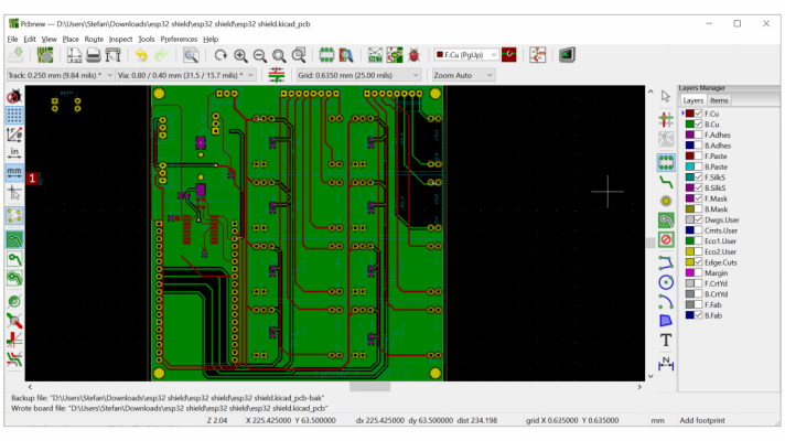
I'm attempting to build one of these with an 4 channel 8up LDD driver board, integrated RTC and hopefully the above fan control circuit to power 4 fans, this is where I'm at now, I'll probably have to redraw it as I've made many changes and the schematic is now incomplete.

I'm trying to keep the board at 100 x 100 mm, right now it 100 x 102 mm, I believe that may increase the cost of fabrication.
 

Attachments

  • Untitled.png
    Untitled.png
    264.3 KB · Views: 60

Keeping it clean: Have you used a filter roller?

  • I currently use a filter roller.

    Votes: 45 29.2%
  • I don’t currently use a filter roller, but I have in the past.

    Votes: 5 3.2%
  • I have never used a filter roller, but I plan to in the future.

    Votes: 42 27.3%
  • I have never used a filter roller and have no plans to in the future.

    Votes: 54 35.1%
  • Other.

    Votes: 8 5.2%

New Posts

Back
Top